
Email: sales@xtalong.com Tel: +86-28-80192520

Email: sales@xtalong.com Tel: +86-28-80192520
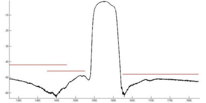
Center Frequency: 1575.42MHz
Insertion Loss: 1.3dB Typ.
Ripple Level: 0.1dB Typ.
VSWR: 1.2
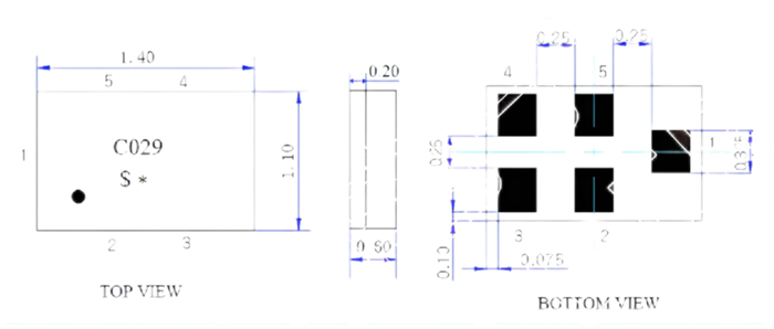
Diemnsion: 1.4 * 1.1 * 0.5MM
SAW filter for GPS.
•High stability and reliability with good performance and no adjustment.
•Narrow and sharp pass band characteristics.
•Low insertion loss and deep stop band attenuation for interference.
•Low – loss SAW filter for GPS.
Items | Rating | unit |
Maximum Working Voltage | 10 | Vdc |
Maximum Working Power | 10 | dBm |
Operating Temperature Range | -40 ~ +85 | ℃ |
Storage Temperature Range | -40 ~ +85 | ℃ |
Items | Test Condition | Min | Typ | Max | Unit |
Center Frequency | - | - | 1575.42 | - | MHz |
Insertion Loss | F0±1.2 MHz | - | 1.3 | 1.6 | dB |
Ripple Level | F0±1.2 MHz | - | 0.1 | 0.5 | dB |
Attenuation | D.C~1476MHz | 42 | 45 | - | dB |
1425~ 1525MHz | 46 | 50 | - | dB | |
1625~1725MHz | 48 | 52 | - | dB | |
1725~1850MHz | 48 | 52 | - | dB | |
1850~2000MHz | 48 | 50 | - | dB | |
2000~3000MHz | 38 | 40 | - | dB | |
VSWR | 1574.22~1576.62MHz | - | 1.2 | 1.6 | - |
Input/Output Impedance | - | - | 50 | - | ohm |

Category | Reliability test items | Test condition | Qty | Description | |
Environment Test | 1 | Low temperature storage | -40±5℃ 240h | 23 | JESD22-A119 |
2 | High temperature storage | 125±5℃ 240h | 23 | JESD22-A103E | |
3 | High temperature humidity | 85℃ 85%RH, 240h | 23 | JESD22-A106B | |
4 | Thermal Shock | -40 /30min~ +85 ℃/30 min 100 cycle | 23 | JESD22-A106A | |
Mechanical Test | 5 | Drop Test | 152mm 12times Steel floor JIG(110g~150g) | 23 | IEC 1178-1.4.8.9 |
6 |
Vibration | 10~55Hz,amplitude 1.5mm Sweep time:1min, X.Y.Z direction, 2h/direction |
23 |
IEC 1178-1.4.8.7 | |
Physical Test | 7 | Soldering heat resistance | Reflow with 260±5℃, 10±1s (Solder Pot) | 23 | JIS C 5201 4.18 |
8 | Solderability test | 235±5℃ 3 sec. (Solder Pot) | 50 | JIS C 5201 4.17 | |
9 | Board adhesion | 0.5mm/sec 1point push | 11 | IEC 68-2-21 Ue3 | |
10 | Leak Hunting | 125℃ Fluorocarbon oil leak Hunting (30±1)s | 20 | MIL-STD-883E 1014.9 | |
Static voltage between signal load & ground may cause deterioration &destruction of the component. Please avoid static voltage.
Ultrasonic vibration may cause deterioration & destruction of the component. Please avoid ultrasonic cleaning
Only leads of component may be solded. Please avoid soldering another part of component.
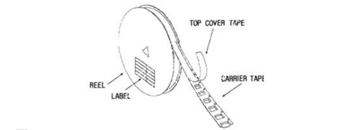
(1) Carrier Tape: Figure 1
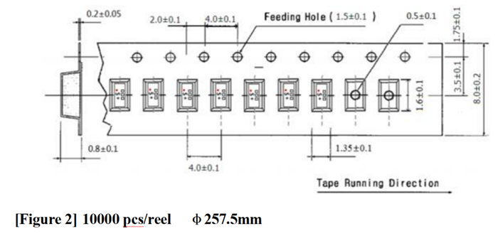
(2) Reel: Figure 2
(3) The product shall be packed properly not to be damaged during transportation and storage.
3000 pcs/reel 7’’
(1) The tape shall be wound around the reel in the direction shown below.
Device Name | |
Marking | |
User Product Name | |
Quantity | |
Lot No. |
(3) Leader part and vacant position specifications.

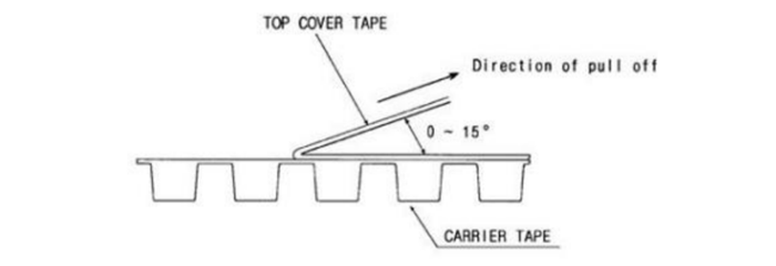
(1) pull off angle: 0~15º
(2) speed: 300mm/min.
(3) force: 20~70g
[Figure 1] Carrier Tape Dimensions
联系人:Katya Vane
手机:+86-18884136031
电话:+86-28-80192520
邮箱:sales@xtalong.com
地址: No.4 of XinHang Road, West of High-tech zone, Chengdu City 611731, China